| Applicable Versions | NetSim Academic | NetSim Standard | NetSim Pro |
| Applicable Releases | v12.1 |
Consider the following network scenario created in the Internetworks Module of NetSim:

Steps followed to create the network scenario:
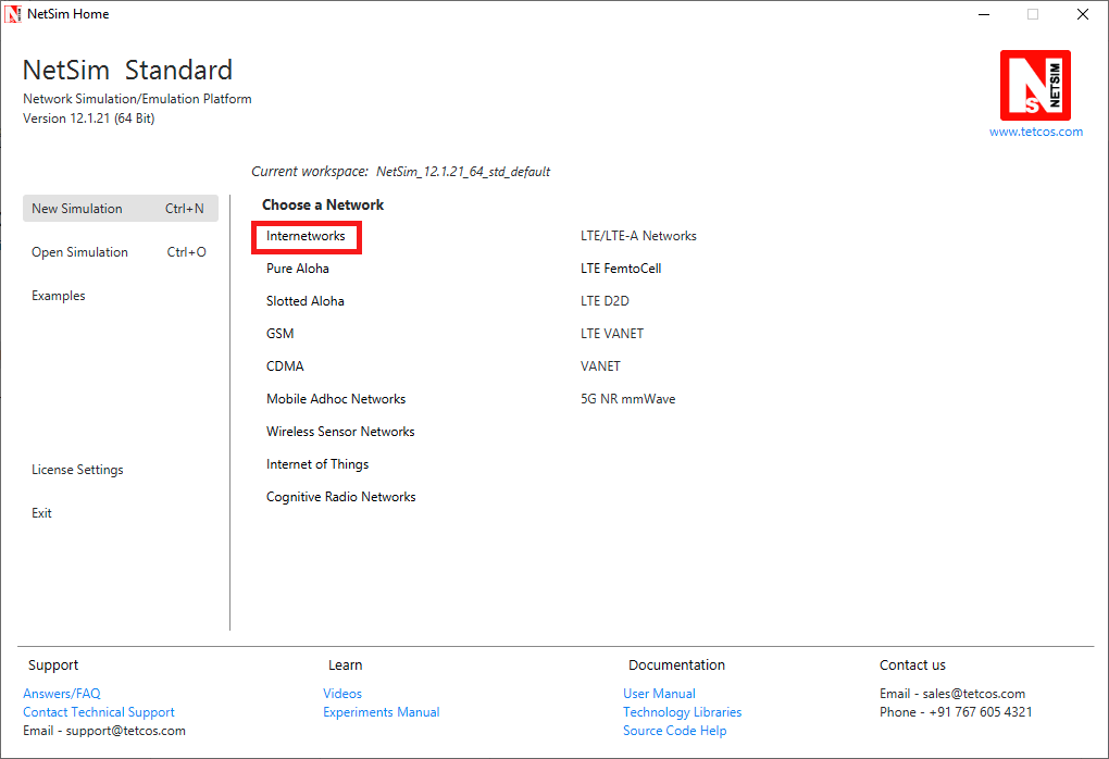
1. Click on Internetworks option under New Simulation option in NetSim Home Screen
2. Click and drop the devices from the panel into the grid
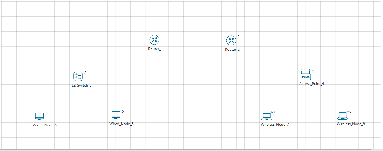
3. Establish link (wired/wireless) between the devices using the Wired/Wireless Link icon in the device panel. Select the link, click on one device, release the mouse pointer, and click on the other device to establish a connection between them. NetSim will automatically connect devices using wired or wireless links based on the type of device.

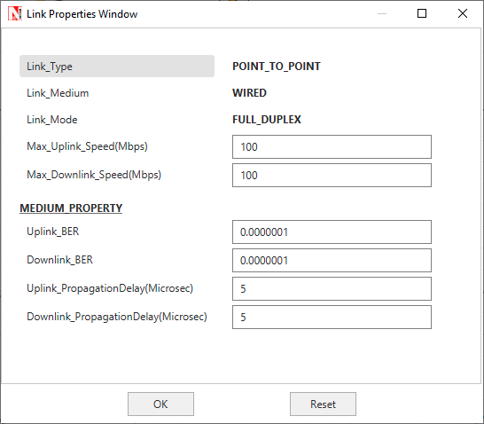
4. Each device and link in NetSim can be individually configured. Right click on any of the wired links (over the Link ID) and select properties.

5. In the Link Properties Window that appears various properties of a wired link such as Link Speed (Mbps), Bit Error Rate, Propagation Delay etc can be configured.
6. In case of wired links between routers(WAN interfaces), link failure model is available, where the link up and down time can be specified to model link failure at specified duration during the simulation:

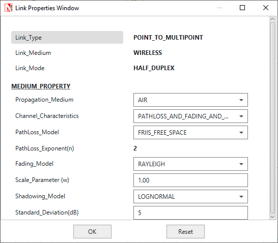
7. The Wireless links support various channel characteristic models such as pathloss, fading and shadowing each with several inbuilt models to choose from
8. To configure a router, right click on it and select properties.

9. Routers in NetSim support OSPF and RIP protocols which can be configured in the Application Layer section of the Router properties Window

10. Router also supports Static route configuration and Access Control List configuration (ACL) in the Network Layer Section.

11. In the WAN interfaces of the router, Scheduling and Queuing type can be set.

12. To configure a Switch, right click on the switch and select properties.

13. The Buffer Size, Switch Priority, Spanning Tree Protocol Cost, Switching Mode etc can be configured in the Data Link layer property seciton of each of the interface that a switch has.
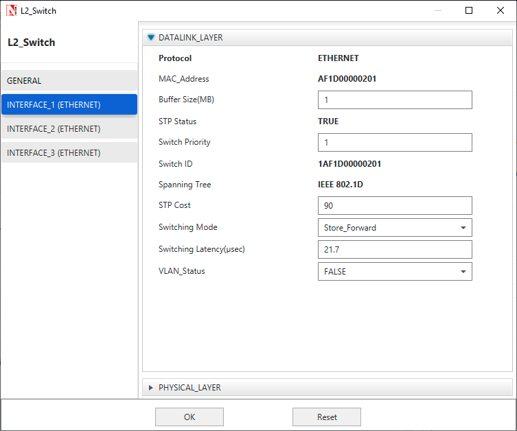
14. Switches also support VLAN configuration which can be accessed by setting the VLAN status to TRUE

15. NetSim also supports L3 switches which additionally support ACL and static route configuration in the network layer similar to the routers

16. After configuring the devices and links Application traffic can be modeled using NetSim's inbuilt virtual traffic generator which is the Application

17. NetSim supports Unicast, Multicast and Broadcast traffic with support for various application models such as CBR, HTTP, FTP, Voice, Video, etc. You can configure multiple applications between different devices in the network. Various properties such as source id, destination id, start time, end time, encryption, priority etc can be configured for each application.


18, Once traffic is configured, you can enable advanced options such as plots and packet trace and Run the simulation using the Run button by specifying the simulation time.
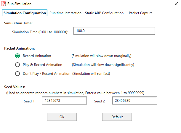
19. After the simulation NetSim provides packet animator and the results dashboard which help in understanding the network performance and get additional insights on the simulation performed.
20. Any simulation done, can be saved and retrieved.
NetSim also comes with several inbuilt examples and experiments which can be accessed from the Examples menu in the Home Screen. Each network technology comes with a set of featured examples and dedicated documentation (can be opened by clicking on the book icon).

Additional References:
- Video - https://youtu.be/3TZs7PfRVt4
- NetSim User Manual
- Technology Library Manuals
- Knowledgebase - https://support.tetcos.com/support/home
