`
| Applicable Versions | NetSim Standard | NetSim Pro |
In 5G simulations, SUMO can be integrated to introduce vehicular mobility in the UEs. This will require modifications to the underlying GUI property files.
| Applicable Releases | v15 |
Steps to add SUMO mobility model for UE's in 5G NR network of NetSim:
Step 1: Download the attached zip folder based on the version of NetSim that you are using (v15.0) and extract the folder to find the following files:
- Experiment File
- UE.xml
Step 2: Go to the location <NetSim-Installation-Directory>/Docs/UI_xml/ Device_Properties. Rename the existing UE.xml file to say, UE _backup.xml as a backup. Then copy and paste the downloaded file in the location.

Step 3: Close and re-open the NetSim application. Now in any of the 5G examples or while creating a new 5G network scenario, you will see SUMO as one of the Mobility model options in the UE General Properties section as shown below.

Running 5G simulations with SUMO integration
In the VANETs module of NetSim, users can directly import a SUMO configuration file and NetSim will automatically add the vehicles to the grid and set the mobility model to SUMO.
However, in this case, since the integration is done manually, UE's will have to be dropped manually and properties will have to be set. An inbuilt VANET example that involves a SUMO configuration file is considered in this article.
1. We consider the example; Example -> VANET -> Simple scenario. The SUMO files are available in
NetSim-Installation-Directory>\Docs\Sample_Configuration\VANET\Simple_Scenario\\Configuration.sumo.cfg

2. To estimate the number of vehicles, the initial vehicle positions, and the simulation grid area, the SUMO configuration can be opened using the VANET module (shown left in the image below point 4.
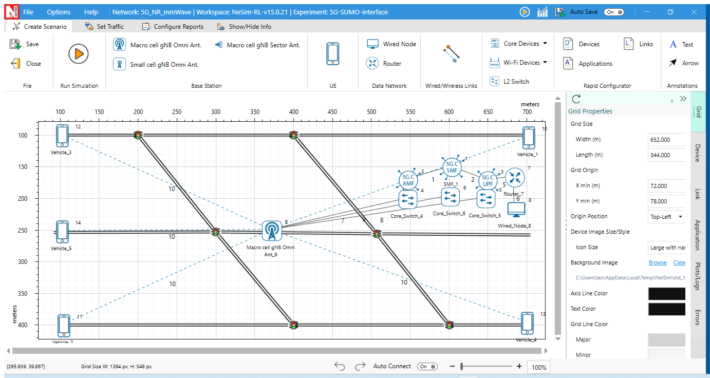
3. After this you can create a new scenario in 5G and set the Grid area and UE positions accordingly. Drop 5 UEs, 1 gNB, 1 EPC. These 5UEs correspond to the 5 vehicles.
4. Connect all UE to gNB and connect gNB to EPC.
NetSim Scenario

SUMO Scenario

5. The UE names should match the names assigned to the vehicles in the SUMO configuration file. In this example UE names are set as 'Vehicle_1', 'Vehicle_2', 'Vehicle_3', 'Vehicle_4', 'Vehicle_5' for UE_1 to UE_5 respectively.
To change the UE names, click on UE Properties > General > Device Name.

The correct naming is important because the position coordinates of the vehicles are retrieved by NetSim from SUMO during runtime based on the device names.
6. Go to Properties of all individual UEs and change the following
Mobility model - SUMO
Sumo File - Configuration.sumo.cfg
Step Size - 0.4
Note: After creating the scenario, close the experiment and open the experiment folder and copy all the associated SUMO files in the experiment ConfigSupport.
<Workspace folder>\<Experiment Folder > ConfigSupport.

7. Reopen the network in NetSim to see the road network background updated as per the VANET network:
8. UE icon can be modified to that of a vehicle if required. For this, right-click on UE-> Open Properties > Graphics > Change Icon

8. Model application traffic flow between UEs and Run the simulation.
A 5G experiment file related to the above explanation is part of the attachment. Users can import experiment file to NetSim after replacing the UE.xml file as explained above.
| Applicable Releases | v14 |
Steps to add SUMO mobility model for UE's in 5G NR network of NetSim:
Step 1: Download the attached zip folder based on the version of NetSim that you are using (v14.0) and extract the folder to find the following files:
- Experiment File
- UE.xml
- VANET-WirelessNode.png
Step 2: Go to the location <NetSim-Installation-Directory>/Docs/UI_xml/ Device_Properties. Rename the existing UE.xml file to say, UE _backup.xml as a backup. Then copy and paste the downloaded file in the location.
Step 3: Close and re-open the NetSim application. Now in any of the 5G examples or while creating a new 5G network scenario, you will see SUMO as one of the Mobility model options in the UE General Properties section as shown below.
Running 5G simulations with SUMO integration
In the VANETs module of NetSim, users can directly import a SUMO configuration file and NetSim will automatically add the vehicles to the grid and set the mobility model to SUMO.
However, in this case, since the integration is done manually, UE's will have to be dropped manually and properties will have to be set. An inbuilt VANET example that involves a SUMO configuration file is considered in this article.
1. We consider the example; Example -> VANET -> Simple scenario. The SUMO files are available in
NetSim-Installation-Directory>\Docs\Sample_Configuration\VANET\Simple_Scenario\\Configuration.sumo.cfg
2. To estimate the number of vehicles, the initial vehicle positions, and the simulation grid area, the SUMO configuration can be opened using the VANET module (shown left in the image below point 4.
3. After this you can create a new scenario in 5G and set the Grid area and UE positions accordingly. Drop 5 UEs, 1 gNB, 1 EPC. These 5UEs correspond to the 5 vehicles.
4. Connect all UE to gNB and connect gNB to EPC.
NetSim Scenario
SUMO Scenario
5. The UE names should match the names assigned to the vehicles in the SUMO configuration file. In this example UE names are set as 'Vehicle_1', 'Vehicle_2', 'Vehicle_3', 'Vehicle_4', 'Vehicle_5' for UE_1 to UE_5 respectively.
To change the UE names, click on UE Properties > General > Device Name.
The correct naming is important because the position coordinates of the vehicles are retrieved by NetSim from SUMO during runtime based on the device names.
6. Go to Properties of all individual UEs and change the following
Mobility model - SUMO
Sumo File - Configuration.sumo.cfg
Step Size - 0.4
Note: After creating the scenario, close the experiment and open the experiment folder and copy all the associated SUMO files in the experiment ConfigSupport.
<Workspace folder>\<Experiment Folder > ConfigSupport.
7. UE icon can be modified to that of a vehicle if required. For this, right-click on UE-> Open Properties > Graphics > Change Icon (Sample Vehicle Icon is attached)
8. Model application traffic flow between UEs and Run the simulation.
A 5G experiment file related to the above explanation is part of the attachment. Users can import experiment file to NetSim after replacing the UE.xml file as explained above.
| Applicable Releases | v13 |
 |  |
| Sumo - GUI | NetSim-GUI |
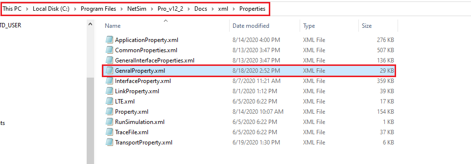
Step 1: Download the attached zip folder based on the version of NetSim that you are using (v12.2/v13.0/v13.1/v13.2/v13.3) and extract the folder to find the following files:
- Experiment File
- GenralProperty.xml
- VANET-WirelessNode.png
 Step 3: Close and re-open the NetSim application. Now in any of the 5G examples or while creating a new 5G network scenario, you will see SUMO as one of the Mobility model options in the UE General Properties section as shown below.

| NetSim Scenario |
 |
| SUMO Scenario |
 |
5. The UE names should match the names assigned to the vehicles in the SUMO configuration file. In this example UE names are set as 'Vehicle_1', 'Vehicle_2', 'Vehicle_3', 'Vehicle_4', 'Vehicle_5' for UE_1 to UE_5 respectively.

Mobility model - SUMO
Sumo File - <NetSim-Installation-Directory>\Docs\Sample_Configuration\VANET\Simple_Scenario\\Configuration.sumo.cfg
Step Size - 0.4


Note:
1. NetSim requires - Begin Value, End Value, and Step-Length Value to perform simulation alongside SUMO simulation.
2. NetSim will not import SUMO configuration files that does not include a time section. The time section consists of the begin, end, and step-length parameters. The accuracy of vehicle movement is dependent on the step length specified.
3. For the end value even if you specify a large value say 10000, simulation in SUMO will end when the last vehicle leaves the network when run with NetSim. This is because beyond this time there is no relevant information that NetSim can extract from SUMO
4. Let us say, the first vehicle in your osm.passenger.trips.xml, leaves the network at 0.5 seconds, however, the step length specified is 0.4 seconds. Therefore, during the first step, there will be no vehicles in SUMO, hence leading to the simulation ending in SUMO at 0.4 seconds itself.
Related articles:
NetSim VANET Webpage